Multi-fiber push-on (MPO) connectors are a mainstay in the data center for parallel optics applications that trans mit and receive data over multiple fibers to support high-speed applications. MPO connectors are typically available with 8, 12, 16, 24, or 32 fibers to support 40 to 800 Gigabit parallel optic applications, where each fiber transmits and receives at 10, 25, 50, or 100 Gb/s.
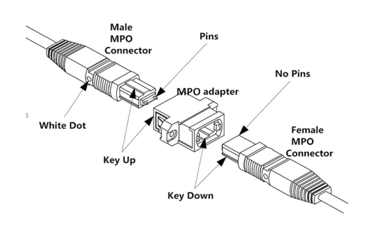
MPO connectors come in male (with pins) and female (without pins) for proper mating and alignment. The MPO interface on active equipment is almost always male. MPO connectors also feature a key on one side of the connector body and a white dot that denotes the first fiber position.
MPO cables can be trunk cables with one or more MPO connectors on both ends. For example, an 8-strand trunk cable has one MPO-8 connector on each end while a 72-strand MPO trunk cable has nine MPO-8 connectors on each end. MPO cables can also be breakout cables with one or more MPO connectors on one end that break out to multiple duplex connectors on the other end, such as one MPO-8 breaking out to four duplex connectors. Breakout cables are ideal for supporting multiple lower-speed connections from a single high-speed switch port, such as a single 100 Gig switch port connecting four 25 Gig servers.
MPO cables are available with Type A or Type B polarity. Polarity ensures that the transmit signals at one end corresponds to the receiver at the other end. Without proper polarity, the data signal will not flow. In this blog, we’ll take a deep dive into the difference between MPO Type A cables and MPO Type B cables to help you understand which is right for you.
MPO Type A Cables
MPO Type A cables feature a straight-through connection, meaning that the fiber in the first position at one end lines up with the fiber in the first position at the other end as shown in the example below. To create this straight-through connection, the MPO at one end is in the key-up position and the MPO at the other end is the key-down position (note the white dot indicating the first fiber position).

MPO Type B Cables
MPO Type B cables feature a reversed connection, meaning that the fiber in the first position at one end lines up with the last position at the other end as shown below. To create this reversed connection, the MPO connectors at both ends are in the key-up position.

How are MPO Type A and Type B Cables Used?
In an 8-fiber parallel optics channel, Positions 5 through 8 of the MPO connector are not used. The fiber in Position 1 (Receive) must correspond to the fiber in Position 12 (Transmit). However, an MPO Type A trunk cable creates a straight-through connection (i.e., 1 to 1, 12 to 12, etc.). To ensure that Position 1 corresponds to Position 12 in a Method A channel, a Type B patch cord must be used on one end of the channel as shown below. This eliminates the ability to use an MPO Type A cable when directly connecting one transceiver to another.

In contrast, MPO Type B cables reverse the fibers, so any odd number of MPO Type B cables can be used throughout an entire Method B channel as shown below. MPO Type B cables support direct transceiver-to-transceiver connections and structured cabling.

As shown below, when extending an existing Method B channel that will result in an even number of segments, an MPO Type A cable will need to be used as it does not impact the pinouts.

When it comes to breakout cables that enable supporting multiple lower-speed connections from a single high-speed port, such as 4X10, 4X25, 4X50, or 4X100 Gig applications, polarity gets a bit tricky. The primary consideration is ensuring that each duplex connector supports both transmit and receive. For example, in an 8-fiber parallel optic application, Fiber Positions 1, 2, 3, and 4 are transmit and Fiber Positions 9, 10, 11, and 12 are receive positions. Breakout cables must therefore provide a physical connection that resembles the following:

Which MPO Cable is Right for You?
Most industry experts recommend maintaining the same polarity throughout a data center for consistency. However, if you’re using MPO Type A with Method A polarity, due diligence is required to ensure that a Type B patch cord is used on one end of all channels.
Method B is typically recommended for any new parallel optics deployment since all Type B cables are used, which limits mistakes and streamlines inventory. Method B is also required for direct transceiver-to-transceiver deployments.
For breakout cables, it’s best to work with your vendor to ensure that the polarity and fiber positions will support your specific application. The following table is a basic summary to help you choose which MPO cables are needed for parallel optics applications from 40 to 800 Gig.


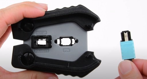
In Method A and mixed data center environments, ensuring proper polarity is more complex. Not using an MPO Type B on one end of a Method A channel is a common mistake that can result in a non-functioning connection. Rather than being stuck with the wrong cable and possibly having to reorder and delay the time it takes to get your equipment up and running, one option for multimode MPO cables is the US Conec MTP Elite Pro connector. This innovative version of an MPO connector lets you change polarity from Type A to Type B or vice versa using a simple tool. It’s important to note that the polarity of singlemode MTP Elite Pro connectors cannot be changed due to the angled APC end face. MTP Elite Pro connectors also let you change gender on both multimode and singlemode connectors using a pin exchanger, so you can easily ensure having a female connector to connect to the male equipment interface.
The good news is that Cables Plus USA offers a wide range of MPO trunk and breakout cables in Type A or Type B, including cables with MTP Elite Pro connectors. If you're still unsure of which type you need for your application and polarity method, our experts are here to walk you through the selection process. We can also custom design your breakout cables to ensure proper polarity for your specific applications. Contact us, and we will be happy to assist you!

