How to Test Fiber Optic Cable
- Oct 8th 2024

Even if your project specification or customer doesn’t require you to test a newly installed fiber cable plant, you could be putting yourself and your customer at risk if you don’t. Certification testing to industry standards ensures that a cable plant will support your customers’ applications and prevent costly callbacks.
Test results for every fiber link are invaluable. They help with troubleshooting and protect your bottom line. If your customer experiences issues with a link months after installation, having original test results provides a benchmark. If the link passed testing initially, the original test results prove the problem isn’t due to your installation. A lot can go wrong with fiber cabling after installation. Other trades or network technicians can damage or mishandle installed fiber, causing severe bends or contamination that degrades performance. Having test results can avoid making repairs at your own expense, maintain your reputation, and improve customer satisfaction.
Test results can also help determine the quality of your own technicians. If one technician’s installed links consistently demonstrate poor test results, it could be due to improper terminations, cleaning, or other inferior installation practices that can be addressed with training.
There are multiple types of fiber optic testing. The type of testing depends on the specification, customer requirements, and the specific goal. The two main types of testing are Tier 1 insertion loss or Tier 2 OTDR certification testing. Let’s take a look at how to conduct these tests.
Tier 1 Insertion Loss Testing
The primary fiber test to ensure compliance with industry standards is insertion loss testing, also known as “Tier 1” certification testing. Insertion loss is the loss of signal strength as it travels along a cable link. It is a positive number measured in decibels (dB) that is calculated by comparing input power at the source to the output power at the far end. Industry standards specify the maximum allowed channel insertion loss for a given multimode or singlemode fiber application. If the insertion loss is too high, the link won’t adequately support the application.
Tier 1 Insertion loss testing is done using an optical power meter and light source. The power meter measures the optical power of the light source signal at the far end of a link. When selecting a power meter and light source, it’s essential to ensure they can support the correct wavelength and fiber type. That typically means testing a wavelength of 850nm for multimode and wavelengths of 1310nm and 1550nm for singlemode. Some wave-division multiplexing (WDM) applications may require testing at additional wavelengths, which may require an optical WDM power meter capable of testing power levels of multiple wavelengths. The power meter should also include the same connector interface (e.g., LC, ST, SC, etc.) as the cabling under test. When testing MTP/MPO fiber cabling links, it’s especially important to choose a MTP/MPO power meter specifically designed to support multi-fiber testing. Using a duplex tester for MTP/MPO links is time-consuming and difficult process that requires an MPO-to-duplex fanout cord or cassette and testing multiple times.
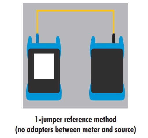
When testing a fiber link, a test reference jumper is used to connect the tester to the link under the test. Before performing the test, the power meter must be set to 0 dB. This is achieved by setting a reference, which takes into account the loss of the test jumper. You can liken it to setting a zero reference with an empty jug before weighing the contents of the jug. To set a reference, connect the light source directly to the power meter with the test jumper, with no adapters between the meter and the source. The meter can then be calibrated to zero, so that when you test the link, the insertion loss of the test jumper is omitted from the results. Most optical power meters feature a “set reference” option or wizard with color diagrams to guide you through this important pre-testing setup process. If you don’t set the reference, your results will be inaccurate and pessimistic, meaning the link might fail testing even if it’s good.
Tier 2 OTDR Testing
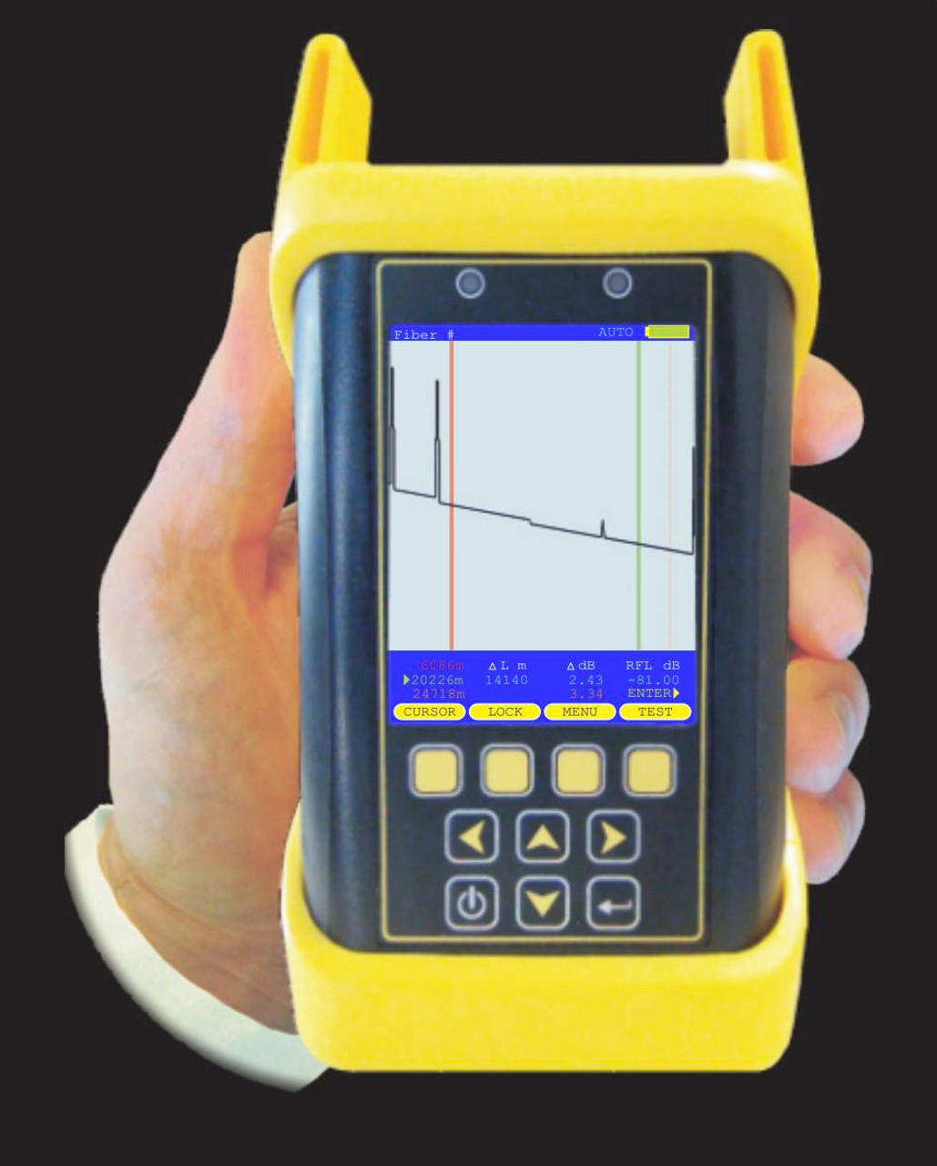
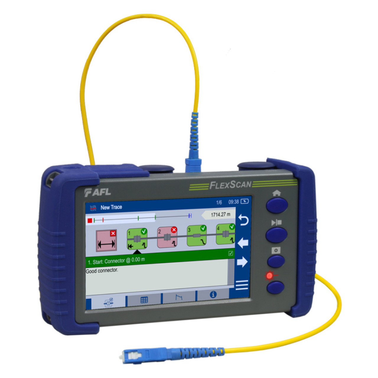
Some specifications and customers may require Tier 2 certification testing with an optical time-domain reflectometer (OTDR) that measures the amount of signal reflected back to the source. Like a power meter, OTDRs must also test at the correct wavelength and fiber type and ensure connector compatibility.
Measuring reflection at both ends of a link (i.e., bidirectionally) with an OTDR provides an estimate of the total insertion loss for the link. An OTDR can also measure the reflection and loss of specific events such as connectors, splices, splitters, severe bends, or breaks in the fiber. These reflections are plotted in an OTDR trace that shows each event and its loss along the length of the link, providing much more detail than Tier 1 insertion loss testing. This allows a technician to identify and precisely locate any bad connectors or splices
Using an OTDR to measure the reflections of specific connectors within a channel is especially useful for newer short reach single mode applications. Low power transceivers used in these applications are highly susceptible to reflectance. In fact, IEEE standards for short-reach single mode applications 200GBASE-DR4/FR4 and 400GBASE-DR4/FR4 specify reflectance values based on the number of connectors in a channel. If the reflectance values can’t be met, the maximum channel insertion loss must be reduced.
Some OTDRs also automatically analyze the trace and provide a simple graphical display that clearly identifies the location, reflectance, and insertion loss of each event. This prevents the need for technicians to be expert OTDR trace readers.
It’s important to note that while Tier 2 testing requires an OTDR, testing total insertion loss with a power meter is still recommended as the final step since it is the only way to accurately calculate total insertion loss of a link. In other words, Tier 2 testing does not negate the need for Tier 1 testing. Most specifications that require Tier 2 testing also require final insertion loss test results with a power meter.
More than Just Certification Testing
White standards-based Tier 1 and Tier 2 certification testing is typically required by specifications to certify a fiber optic cable plant, there are other types of fiber testing that can be performed to help ensure performance and application support.
Before installing fiber, you can test the cable on the reel to ensure you didn’t get a bad batch or that it wasn’t damaged during shipping. If only one end of the fiber on the reel is accessible, you can still use an OTDR to perform a single-ended test that calculates length and identifies any major loss events. While testing from one end won’t provide accurate results, it should provide enough information to prevent you from installing damaged cable.
A visual cable verifier is a great way to quickly and easily test polarity and continuity of an installed cable plant. This is especially beneficial for MPO/MTP deployments where ensuring polarity is more complex due to cables being available with Type A or Type B polarity and the need to ensure that multiple transmit fibers correspond to their receive fibers.
After initial testing and once a fiber optic cable plant goes live, things can still go wrong that cause underperforming or non-functional links. Fiber optic testers can also be effective troubleshooting tools, especially OTDRs for locating bad connectors or splices. There are also a variety of fiber optic troubleshooting tools for identifying cable faults and contaminated connector end faces.
The good news is that CablesPlus offers a complete range of fiber test equipment tailored to all your needs. Whether you need to conduct Tier 1 or Tier 2 certification testing, verify polarity, locate faults, or clean and inspect fiber end faces, CablesPlus has the solution for every application. Contact us today for all your fiber testing needs.
Explore Our Complete Range of Fiber Test Equipment Contact an Expert