CablesPlus USA is the best place to find the MTP/MPO Fiber Optic Cables you need quickly and easily. Our visual guide will assist you in finding the right MTP cable to match your specific needs. We offer MTP fiber optic cable solutions that meet the ever-growing bandwidth and space-efficiency demands of the data center and telecommunications office. Here you will find descriptions and illustrations of the available options for custom MTP/MPO cables.
| Fiber Optic Strand Count |
|
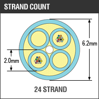
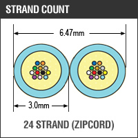
Strand Count is the number of strands of optical fiber within the cable. Typically one pair (one fiber to transmit data and one to receive data) of fibers gives users duplex communication equal to one 8 pair copper patch cable. These cables are manufactured with 12 to 144 strands in a single jacket. How many strands you require will depend on how many strands your equipment requires and how much you want to account for redundancy and expansion you want. Current strand counts offered are: |
||
 |
 |
 |
 |
 |
 |
 |
 |
 |
| Fiber Optic Glass Type |
 |
|
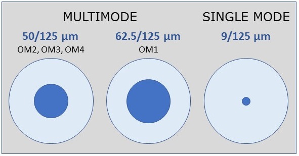
| Singlemode 9/125 Singlemode optical fiber designated by the TIA as OS1. Singlemode fiber has a core size of 8 – 10 microns with a cladding size of 125 microns. Designed for long distance transmission (10km or more) of data with a laser driven system. |
|
| Multimode 62.5/125 Multimode fiber designated by the TIA as OM1. 62.5/125 fiber has a core size of 62.5 microns with a cladding size of 125 microns. Rated for data transmission of 10Mb – 1Gb per second. Mostly used in optical networks spanning short distances (1Gb/s at 850nm for 300m). Largely used with LED based transmission equipment. |
|
| Multimode 50/125 Standard Multimode fiber designated by the TIA as OM2. 50/125 fiber has a core size of 50 microns with a cladding size of 125 microns. Rated for data transmission of 10Mb – 1Gb per second. Mostly used in optical networks spanning short distances (1Gb/s at 850nm for 600m). Largely used with LED based transmission equipment. |
|
| Multimode 50/125 10 Gig (OM3/OM4) Multimode fiber designated by the TIAA as OM3 or OM4. 50/125 fiber has a core size of 50 microns with a 125 micron cladding. Also known as 10 Gig fiber or Laser Optimized Fiber, OM3/OM4 fiber has been designed to interface with laser data transmission systems with performance specified as up to 10 Gigabytes/second. Backwards compatible with Multimode 50/125 Standard OM2. |
|
| Fiber Optic Connectors: Side A |
|
MTP® Connectors MTP brand secure connectors are "keyed" identifiable by color. We currently offer 4 different types of secure MTP brand connectors: Green, Yellow, Red, and Blue. Each connector is only matable with adaptors of that same "key" or color. This provides end-users with peace of mind knowing that their fiber infrastructure is safe from intruders trying to steal data through their hardware. |
| Fiber Optic Connectors: Side B |
|
MTP® Connectors |
|
LC Connectors |
| SC Connectors Originally developed by NTT, the SC connector has a push/pull snap fit. The duplex SC connector (two simplex SC connectors clipped together) uses the same mating profile as the simplex design. |
| ST Connectors Developed by AT&T, the ST connector (for Straight Tip) has been a perennial favorite for its termination simplicity and low cost. |
|
MTRJ Connectors |
| Fiber Optic Jacket Rating |
|
Plenum cables are held to the most stringent testing of any of the cables rated by the NEC, rated for both flammability and smoke generation. Cable jacket fire ratings are something often overlooked when your cable purchase is made, only to be scrutinized by building inspectors after the installation. The National Electric Code articles 700-800 specify flammability ratings for certain installation situations, but muddle the issue by allowing substitutions to be made among their rating systems. A Plenum is defined as any enclosed area that facilitates environmental air handling. An example would be an air conditioning duct or an air routing drop ceiling. However, a plenum can be any air space between walls, under floors, or above non air handling dropped ceilings if duct work is not sealed correctly. |
| Fiber Optic Applications |
|
Fiber optic technology can be used for a myriad of applications, and can be found in nearly all aspects of everyday life. The primary use for fiber optic technology is the fast, efficient transmission of data. This ranges from large-scale corporate global networks that handle sensitive financial and personal information, to consumer internet and high-definition cable television service. |
|
Aerial |
|
Burial |
| Indoor Indoor fiber optic cable is typically used for network patching and building wiring applications. For these applications, indoor fiber optic cabling must able to meet flexibility and strain demands for installation in walls, plenum air handling ducts, and between floors. |
| Military Fiber optic cables undergo rigorous testing to ensure high performance across an array of Military projects, spanning between air, ground, sea and space operations. We work to ensure our fiber cable builds are constructed to meet the strict standards of quality for all U.S. Military applications. |
|
Universal Indoor/Outdoor |
| Fiber Optic Cable Construction |
|
MicroCore® fiber optic cables provide a unique blown solution to crowded underground ducts where traditional cable designs are not an option. MicroCore cables are smaller than traditional loose tube optical cables and can be blown into otherwise full ducts, expanding the capacity of existing infrastructure which translates into less expense and faster deployment. The Microcore product line is a complete solution with a range of designs suitable for applications ranging from backbone networks to FTTx. Microcore cables are jetted or blown through a network of microducts using compressed air. Conduit systems can be laid and microducts blown in as needed, giving installers the flexibility of deploying fiber only when needed, thereby reducing the initial investment costs. Microcore can also be used for "overriding" existing networks and conduits, which might otherwise be deemed as "at capacity". The flexible, lightweight cable design which has a low friction jacket allows it to be blown over existing cables within a duct, thereby expanding the capacity of that duct which would have otherwise been deemed full. |
| Fiber Optic Pulling Eye |
|
The Fiber Optic Pulling Eye is an essential component when working with installation conduits, ducts or risers. Quite simply, a fiber optic pulling eye allows you to pull pre-terminated fiber cable through tight spaces properly, without damaging the fiber core. Using a pulling eye can also keep the fiber connector well protected for runs of up to 2000 feet. For a safe, stress-free installation, a fiber optic pulling eye is a must-have tool. |
| Fiber Optic Breakout Styles |
|
Breakout-style (or fanout-style) fiber optic cable, often referred to as just "breakout cable", is basically several jacketed simplex fibers packaged individually inside one jacket. This differs from distribution style cable, in which several tight-buffered fibers are bundled together within the same jacket. The design of the breakout-style cable adds strength to the cable for ruggedized drops. Staggering refers to a change in the breakout length of each fiber in a multi-fiber or ribbon fiber assembly. A staggered breakout cable is typically used in applications where the cable must be routed to one side rather than from the front of a given port. The stagger allows connector/port mating while allowing for differing distance from port to cable transition. |
| Fiber Optic Breakout Length |
|
In terms of length, the reinforced nature of the breakout style allows you to breakout individual cables at any point in the run. However, Breakout cable is suitable for short riser and plenum applications and also for use in conduits, where a very simple cable run is planned to avoid the use of any splice box or spliced fiber pigtail. |
| Fiber Optic Cable Polarity |
|
Correct fiber polarity insures that light transmitted by a transceiver is received into the correct port on the opposite end of the circuit. Flipped Straight-Through Rollover |
||
