
Every network today includes fiber optic cable and connectivity—whether it’s an all-fiber outside plant (OSP) infrastructure, thousands of fiber links between equipment in the data center, or the fiber backbone in a LAN. While fiber provides greater reach and bandwidth than copper, you may be surprised to learn that fiber is also more durable than copper—even though it’s made of glass. Fiber is immune to electromagnetic interference, offers better corrosion and moisture resistance, and can withstand a tighter bend radius, greater pulling force, more pounds of pressure, and more temperature changes as compared to copper. But that doesn’t mean that things can’t go wrong. The most common causes of an underperforming or non-functional fiber link include:
- Exceeding the loss budget
- Contaminated connector end faces
- Connector misalignments
- Fiber cable faults
- Improper polarity
Exceeding the Loss Budget

Insertion loss, measured in decibels (dB), is the energy a signal loses as it travels along a fiber link. Insertion loss increases with length, and any connection point in a fiber link also adds insertion loss. Specific fiber applications have maximum channel insertion loss and length requirements. Newer short-reach singlemode applications like 100GBASE-DR, 200GBASE-DR4, and 400GBASE-DR4 also have different insertion loss maximums based on the number and reflectance of the connectors in the channel. Reflectance, measured in negative dB, is the amount of reflected signal compared to the source signal and can lead to high insertion loss. Fiber connectors have a specified reflectance that is typically -35 dB or less for multimode and -50 dB or less for singlemode.
It’s essential to calculate insertion loss budgets during the design phase based on the application requirements, the loss and length of the fiber (typically about 3 dB/km for multimode and about 0.5 dB/km for singlemode), and the loss (and sometimes reflectance) of each connection point within the channel. Insertion loss testing using an
optical power meter should be conducted after installation, and it’s the first step when troubleshooting fiber issues. If the insertion loss exceeds the loss budget, it could be due to budget miscalculations during the design phase or changes during installation, such as exceeding the maximum link length or adding too many connection points.
Contaminated Connector End Faces

Any dirt, dust, scratches, or pits on a fiber connector end face will impede light signals from having a clear path along a fiber link, causing higher insertion loss and reflectance. Even if a fiber end face was clean during installation, any time a fiber connector is handled during moves, adds, and changes, it is subject to contamination.
The best way to identify contaminated connectors is to use a hand-held optical inspection scope that magnifies fiber end faces (typically 200X or 400X) for analyzing defects. There are also intelligent inspection systems that automatically analyze cleanliness based on industry standards. For multi-fiber push-on (MPO) connectors where multiple fiber end faces need inspecting, it’s far more efficient to use an MPO inspection solution that automatically scans each fiber. If a connector is contaminated, it should be cleaned using a fiber optic cleaner and reinspected. If the contamination cannot be removed, such as with a deep scratch or pit on the end face, the connector will need to be replaced.
Connector Misalignments
Connector misalignments occur when the fiber cores of two connectors are not precisely aligned, which causes reflectance and insertion loss. Connector misalignments can happen when connectors are not properly and fully mated. This can also cause air gaps between two connectors, which increases insertion loss and reflectance.
Poor connector end face geometry and mechanics can also cause misalignments. Industry standards specify end face geometry, which includes the roundness, the center apex, and the protrusion height of the end face. For MPO connectors with multiple fibers, geometry also applies to how the individual fibers compare to each other. For example, all the fiber end faces in an MPO connector must be as close to the same protrusion height as possible to achieve proper alignment. Connector guide pins must also be mechanically sound to maintain alignment and provide the proper amount of force needed to maintain a connection. Connector misalignments due to poor end face geometry can be resolved using higher-quality connectors such as MTPs connectors from US Conec with more precise end face geometry requirements. If you’d like to learn more about end-face geometry, read our MTP vs. MPO blog article.
Troubleshooting Fiber Cable Faults

Faults in a fiber cable can happen due to overbending and damage during installation. Exceeding the bend radius for the fiber can cause light signals to leak out of the fiber core, which leads to high insertion loss. Bends can even cause the glass to crack or break, preventing signal transmission altogether. Note that during installation (i.e., under tension), the minimum bend radius is 20X the diameter of the cable. After installation (i.e., under no tension), the minimum bend radius is 10X the diameter of the cable.
A visual fault locator (VFL) is a simple way to locate faults. VFLs come in a variety of styles, from simple compact pen-style VFLsfor checking individual fibers to more advanced solutions that check all fibers within an MPO/MTP arrayed fiber cable at once. VFLs work by emitting a visible bright red laser beam of light down the fiber link that becomes visible at any break or major bend in the fiber where the light leaks out. While minor bends can be rectified by physically straightening out the fiber cable, severe bends, cracks, or breaks require repairing the fiber with a fiber splice or replacing the fiber link altogether.
 test equipment")
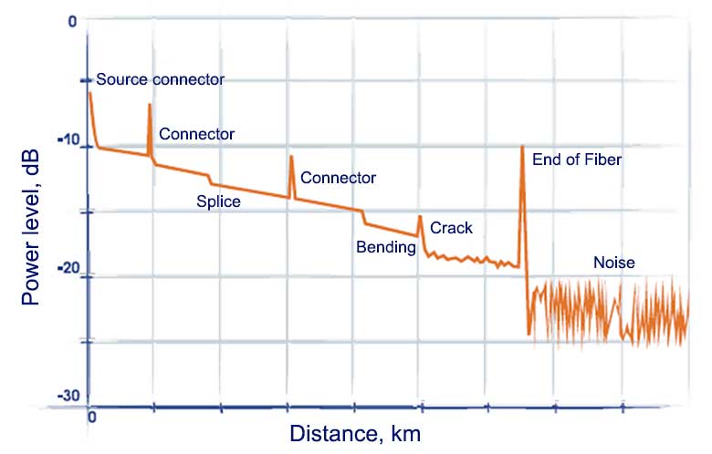
VFLs are not always ideal for locating faults in very long links, in environments where the cable isn’t visible (e.g., behind walls, underground, etc.), or if the cable jacket doesn’t allow the VFL laser light to penetrate (e.g., armored cabled). Faults that can’t be pinpointed with a VFL can be found using an optical time domain reflectometer (OTDR). An OTDR is the best tool for troubleshooting any problems in your fiber network because it provides a comprehensive link trace to show the precise location of loss and reflectance events, such as connectors, splices, bends, and cracks over the entire distance of the link as shown below.
Improper Polarity
In every fiber application, polarity ensures that the transmit signal at one channel end corresponds to the receiver at the other. If the polarity is wrong, the link won’t function. Polarity problems can crop up during moves, adds, and changes if the wrong type of patch cord is used. It’s especially tricky in multi-fiber MPO/MTP applications where multiple fibers at the transmit side of a link need to all correspond correctly to the receive side of the link. Since VFLs check for continuity, they can also be used for checking polarity. More advanced fiber test equipment can quickly verify the polarity of installed MPO/MTP links.
One of the easiest ways to prevent mishaps with polarity is to use connectivity that supports changing polarity in the field rather than purchasing new components. For example, MTP Elite Pro fiber patch cords can change polarity from Type A to Type B and vice versa using a simple tool. You can learn more about polarity by checking out our last blog post on MPO Type A vs. MPO Type B.
The Right Solutions Are Essential
Troubleshooting fiber problems can be complicated, but having the right solutions can simplify the process. The good news is that CablesPlus USA offers a wide range of fiber test equipment, inspection equipment, and fault locators to help you identify fiber network problems. You can also count on CablesPlus USA for everything you need to fix your fiber network cable problems—from cleaners for contaminated end faces and fusion splicers for repairing breaks to a full range of quality fiber cables and connectivity for upgrades and replacements. Contact us, and we will be happy to assist you in finding the best solution for troubleshooting and solving all your fiber network problems.