In a previous blog, we discussed how multi-fiber push-on (MPO) connectors support 400 and 800 Gigabit applications and beyond. A mainstay in the data center, these connectors use a linear array of fibers in a single ferrule for improved density and to support parallel optic applications that transmit and receive over multiple fibers to achiever faster transmission rates. For example, an 8-fiber or 12-fiber MPO can support 40, 100, 200, and 400 Gigabit applications with 4 fibers each transmitting at 10, 25, 50, or 100 Gb/s second and 4 fibers each receiving at 40, 100, 200, and 400 Gb/s.
When we talk about MPO connectivity, we often refer to MTP® connectors, which is an MPO connector developed by US Conec with improved specifications. In other words, all MTPs are MPOs but not all MPOs are MTPs. But what exactly is the difference between an MPO and MTP and why should you care?
Let’s take a closer look.
Geometry Matters
The geometry of a fiber end face has a direct impact on how well two fibers will mate when connected and therefore how well light signals will transmit from one fiber to another. Poor end face geometry can result in air gaps or misalignment between two fibers that can cause higher insertion loss and reflectance. Insertion loss is the loss of signal power and reflectance is the amount of the signal reflected from a connection point, and they are the two most critical performance factors in any fiber optic network.
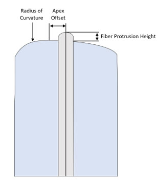
 Industry standards define specific parameters for end face geometry. For a single fiber end face, the IEC 61300-3-35 standard specifies the following properties:
- Radius of Curvature – This is the roundness of the end face. Too tight of a curve can cause too much compression during mating, while too loose of a curve can cause not enough.
- Apex Offset – This is how close the apex of the end face is centered and is determined by measuring the distance (in microns) between the center of the fiber and the peak of the polished end face. The lower the offset, the better the core-to-core alignment.
- Fiber Protrusion Height – Specifies how high the fiber core extends from the surface. Too high of a protrusion can damage the fiber during mating, while too low of a height can cause air gaps.
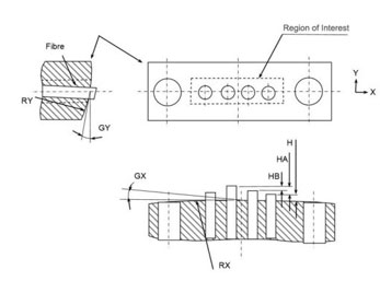
For MPO connectors, geometry gets a bit trickier since these specifications now need to be applied to all of the fibers within the array. To achieve proper geometry, each of the fibers in the array also needs to be compared to all other fibers. They need to have as close to the same protrusion height and angle of polish both horizontally and vertically across the array to achieve proper alignment. And the more fibers in the MPO array, the more difficult it is to achieve geometry—achieving proper geometry is more difficult in a 24-fiber MPO than a 12-fiber MPO. For MPO connectivity, the IEC 61755-3-21 specifies the following properties as shown in the graphic below (note that only 4 fibers are shown for clarity):
 Angle of the polish - Horizontal or X axis (RX and GX)
- Angle of the polish - Vertical or Y axis (RY and GY)
- Fiber Protrusion Height (H)
- Maximum Fiber Protrusion Height Differential Among all Fibers (HA)
- Maximum Adjacent Fiber Protrusion Height Differential (HB)
All MPO connectors have improved in their overall geometry since first introduced for FTTX applications to support ribbon fiber deployments in the 1990s. All MPOs should also meet the IEC standards for end face geometry. However, when it comes to the MTP version, US Conec has slightly more stringent requirements for RY, GX, HA, and HB specifications. For example, the IEC specifies a maximum fiber height differential among all fibers of less than or equal to 0.0005 mm, while US Conec specifies less than or equal to 0.0004 mm. The IEC specifies a maximum adjacent fiber height differential of less than or equal to 0.0003 mm, while US Conec specifies less than or equal to 0.0002 mm.
With more precise end face geometry requirements, the MTP provides superior insertion loss and reflectance, which is critical for supporting higher-speed applications that have much more stringent loss requirements. It’s especially critical in newer short-reach singlemode applications like 200GBASE-DR4 and 400GBASE-DR4 that we discussed in use lower-cost transceivers that are more susceptible to reflectance. In fact, for short-reach IEEE specifies insertion loss limits based on the number and reflectance of connections in the channel. US Conec also has an MTP Elite line of connectors with even more stringent requirements and a lower insertion loss performance.
It's Also in the Mechanics
The overall mechanical design of a fiber connector also plays a role in how well two connectors can mate, as well as overall reliability. No matter how precise the fiber end face geometry, if the guide pins used to mate two connectors do not ensure accurate alignment, the fiber cores won’t line up and the result will be poor insertion loss and reflectance. The guide pins on an MTP connector use stainless steel elliptical guide pin tips rather than flat tips used in other MPO designs. The elliptical edge of the MTP pins is more reliable and reduces the amount of debris that can build up in the guide pin holes and throw off alignment.
Another key difference is in the pin clamp that holds the pins in place. The MTP connector uses a recessed metal pin clamp that ensures a strong hold on the pins, while other MPOs use a plastic pin clamp that may not hold up to multiple matings over time. While industry standards specify a minimum of 500 matings, MTP® connectors under normal use and proper cleaning can withstand well over 1000 matings.
There are additional mechanical differences that make the MTP superior. The spring of the connector provides the force needed to maintain the connections of two mated connectors. In the MTP connector, the spring is slightly wider to maximize clearance for ribbon fiber, and the end of the spring is also better secured. This design prevents the spring from damaging the terminated fiber. It also better centers the spring force and eliminates lost pins.
The ferrule that surrounds the fibers also differs on the MTP in that it uses a patented floating design that allows fibers to maintain contact under load. This is especially important when mating a connector directly to a switch and is one of the reasons many switch manufacturers prefer the MTP for their I/O interface. US Conec also uses a polyphenylene sulfide thermoplastic injection molding for its ferrule that is more resilient to fluctuating temperatures and better maintains its structure and guide hole diameter. It is also less prone to moisture absorption compared to other thermosetting technology that can degrade over time.
The Overall Better Choice
Another key difference in the MTP connector compared to other MPOs is that the housing is removable. This allows customers to re-work and re-polish the ferrule if necessary. It also allows for changing the gender and polarity of the connector in the field, which is supported with the MTP Pro connector and tool that allows for easily removing or inserting pins or changing polarity. US Conec also offers different variations of strain relief boots to support a variety of applications and fiber types including round, loose fiber cable, oval jacketed cable, and bare ribbon fiber.
In summary, because the MTP offers superior performance and reliability, it should be a consideration when purchasing any MPO fiber cable assemblies or cassettes—especially if you’re deploying advanced high-speed applications where insertion loss and return loss performance are more critical than ever.
The good news is that because CablesPlus USA is committed to providing our customers with the highest quality fiber optic products, we use high-performance MTP Elite connectors as our connector of choice for all our MPO solutions, including our high-density HD8² ultra-high density system. To learn more, just contact us at sales@cablesplususa.com or 866-678-5852.

