Fiber Insertion Loss, What it is and How to Reduce It
- Feb 16th 2024
- By
Fiber insertion loss (sometimes referred to as attenuation) is a primary performance factor in fiber optic transmission. Industry standards specify the maximum channel insertion loss for specific fiber applications and channel length. Exceeding the loss requirements can increase bit error rates or prevent your fiber network links from functioning altogether. Therefore, it’s essential to understand insertion loss and how to reduce it.
What is Fiber Insertion Loss?
Insertion loss, measured in decibels (dB), is the amount of transmitted power an optical signal loses as it travels down the fiber. Insertion loss is, therefore, directly related to length—the longer the channel length, the greater the loss of signal power at the receiver end. If too much signal power is lost, the receiver at the far end cannot correctly decipher the signal. Insertion loss also increases as the signal passes through any connector, splice, or splitter. That’s why data center designers create loss budgets based on the insertion loss value of the fiber cable, channel length, and the insertion loss values for each connection point. Dirty fiber connector end faces and bends within the cable can impede the signal and also increase insertion loss.
Insertion loss increases with transmission speeds, so channel insertion loss and length requirements have become increasingly stringent. For example, while 10GBASE-SR supports 10 gigabits per second (Gb/s) to 400 meters over multimode fiber with a maximum channel loss of 2.9 dB, 100GBASE-SR4 supports 100 Gb/s to only 100 meters with a maximum channel loss of just 1.9dB.
Following installation, testing all fiber links is essential to ensure the insertion loss doesn’t exceed the specified maximum for a given application. Referred to as Tier 1 testing, this is achieved using fiber optic test equipment such as an optical loss test set or power meter that compares the power of the source signal to the power available at the far end. Tier 1 testing of every fiber link is almost always required as part of a project specification—whether it’s a short high-speed link in the data center or a long backbone link in a LAN or WAN.
How to Reduce Fiber Insertion Loss
With increasingly stringent channel insertion loss requirements, keeping the loss as low as possible is essential to ensure network performance. Multiple design and installation best practices can help ensure you don’t exceed the limits.
Keep Your Fiber Connector End Faces Clean
As discussed in our blog on fiber end face contamination, dirty fiber end faces can cause insertion loss. Any speck of dust can block some portion of a light signal from properly transmitting through the connection. That’s why it’s imperative to always properly clean and inspect connector end faces using appropriate fiber optic cleaners and optical inspection equipment.
Avoid Exceeding Cable Bend Radius and Tension Requirements
Micro and macro bending of fiber cable that can occur during installation should be avoided to keep insertion loss at a minimum. Macrobends are typically caused by not maintaining the maximum bend radius when routing fiber cables through pathways and cable management. Microbends are a bit trickier—these bends generally are caused by placing too much tension on the cable when pulling. They can go unnoticed upon initial testing but worsen over time. Microbends can even eventually cause the glass to crack, preventing signal transmission altogether.
Reduce Overall Channel Length and Connections
Because insertion loss is directly related to length and caused by every connection point, reducing the overall channel length or number of connection points can prevent exceeding insertion loss limits. Using concatenated link segments via patch panels between equipment in data center environments can result in too many connection points that push insertion loss above the budget. Even if the insertion loss falls within the application limits, it’s essential to maintain enough headroom to account for contaminated connector end faces and cable bends.
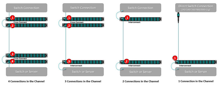
In the data center, designers may need to consider using interconnects for distributing fiber from equipment rather than cross-connects to reduce the number of connections. As shown below, using cross-connects at both ends of the channel adds four connections, while using an interconnect at one end results in a 3-connector channel. Using interconnects at both ends results in a 2-connector channel, and using a direct switch connection with an interconnect at the server results in a 1-connector channel. Additionally, splices have less loss than connectors. So, wherever you’re deploying permanent connections that don’t need to change (such as where incoming service provider fiber comes into the data center), fusion splicing may be the way to go.
Choose Quality, Low-Loss Fiber Components
You can also help reduce insertion loss by using quality, low-loss components. While fiber connectivity varies from vendor to vendor, most fiber optic connectors are available in standard and low-loss versions. If you need more connection points in a channel to support cross-connects, choosing low-loss connectivity can prevent exceeding insertion loss requirements. For example, in a 100GBASE-SR4 deployment with a maximum insertion loss of 1.9dB, standard loss LC connectors at 0.4dB could limit you to just three connectors in the channel since you also need to consider fiber cable loss and headroom. In contrast, using low-loss LC connectors at 0.15dB or less allows for more than twice the number of connectors.
Choosing components from reputable sources that use quality components and stand behind their insertion loss specifications is also important. Cheap, low-quality components may exhibit higher insertion loss due to poor connector end-face geometry, misalignment, or lack of mechanical reliability.
Look to Innovative Fiber Technologies
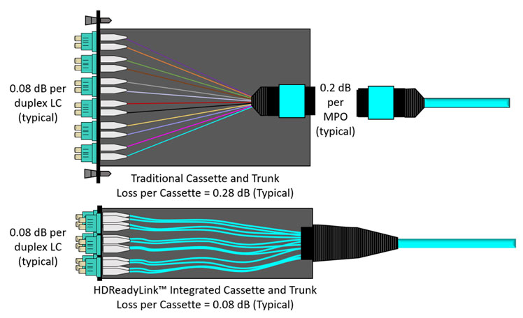
Innovative fiber technologies that can help reduce insertion loss are available. In duplex and breakout applications, it’s common to use plug-and-play MPO-to-LC cassettes at fiber patch panels. However, these cassettes include the loss of the MPO connection at the rear of the cassette and the loss of the LC connection at the front. To significantly reduce insertion loss associated with cassettes, Cables Plus USA developed HDReadyLink™ cassette trunks as part of our HD8² Ultra High-Density Solution. The HDReadyLink integrates the cassette and trunk into a single component, eliminating the rear MPO connection and its associated insertion, as shown below. This innovation can allow for more connection points and/or headroom within a channel.
The good news is that CablesPlus USA doesn’t just offer innovations like our HDReadyLink™ cassette trunks. We are also fully committed to providing the highest quality fiber solutions, which is why we only use premium-grade, low-loss fiber components like Senko and US Conec connectors. Plus, we have the cleaning, inspection, and test equipment for all your fiber optic needs. And if you need help calculating insertion loss budgets and choosing the right components to ensure maximum performance, we’re always ready to help.