

The Complete Checklist for Ordering Custom Fiber Cable Assemblies
- Nov 19th 2026
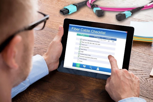
The Complete Checklist for Ordering Custom Fiber Cables
Cables Plus USA is your premier partner for custom fiber-optic cable assemblies tailored to your unique applications. As network infrastructure grows increasingly complex, navigating fiber cabling requirements is more challenging than ever. While our team of experts is always available to help define your exact specifications, understanding and determining the core variables upfront helps streamline the process.
Before placing your next custom cable order, use this essential checklist to improve accuracy, avoid costly procurement errors, and ultimately ensure fiber infrastructure that meets your precise requirements and delivers seamless, high-performance signal transmission.
Table of Contents
- Application, Deployment, and Environmental Factors
- Glass Type
- Connector Specifications
- Polish Type
- Cable Construction
- Strand Count
- Jacket Rating
- Cable Length
- Fanout/Breakout Length and Style
- Polarity
- Additional Specs
1. Application, Deployment, and Environmental Factors
Fiber optic cables are used in a myriad of applications, from data centers, LANs, and large-scale global networks to high-definition TV broadcasting, military, aerospace, industrial, shipboard, and more. Application, deployment, and environmental factors are primary variables to consider when ordering custom fiber cables, as they can impact subsequent variables such as fiber construction and jacket rating.
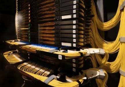
Indoor (Premises): Indoor fiber is deployed in data centers to establish switch-to-switch and switch-to-server links, typically via patching areas. Within LANs, they serve as backbone cabling between telecom rooms, frequently traversing floors via risers and crossing floors via plenum air-handling spaces or walls. Indoor cables can also be used for horizontal LAN cabling, extending from telecom rooms to individual workstations (i.e., fiber-to-the-desk) or to multi-workstation zones. These cables offer the flexibility required for tight indoor spaces while complying with applicable building fire codes.
Outdoor (Outside Plant): Used in outdoor locations, these cables enable service provider networks, connect campus buildings, interconnect data centers, and establish links to homes, businesses, and cellular towers. To ensure physical durability, they must withstand outdoor elements such as sunlight, moisture/water, and extreme temperatures. Their precise characteristics vary based on the specific deployment method:
-
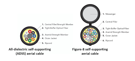
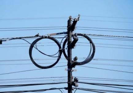
Aerial: Aerial cables are designed to withstand ice, moisture, corrosion, and wind. They can be either all-dielectric self-supporting (ADSS) or figure-8 self-supporting cables. ADSS cables are designed for high-tension or long-span installations along overhead transmission towers and distribution power lines, relying on internal strength members to bear the weight. Figure-8 self-supporting cables are designed for shorter-distance applications along utility poles and between buildings, featuring an integrated messenger cable that eliminates the need for cable lashing and reduces installation time and cost by about 50%. NOTE: The distance between poles or buildings is an essential specification to ensure the cable can support the span.
- Direct burial: These outdoor fiber cables are placed underground without conduit, requiring a highly rugged metallic armor construction to resist shifting earth, heat, moisture, rodents, and other environmental factors.
- Conduit: Outdoor fiber cable placed in conduit does not require as much physical protection since the conduit shields the cable from dirt, shifting earth, and rodents.
Indoor/Outdoor: Indoor/outdoor fiber cables are incredibly versatile, meeting both outdoor durability demands while retaining the flexibility to be routed indoors. These cables eliminate the need to transition from outdoor to indoor cable when connecting locations in proximity, making them ideal for connecting outdoor LAN devices like surveillance cameras and Wi-Fi access points.

Military (Naval, Tactical, Aerospace): Fiber cables are used in a range of military applications, from tactical ground-level field use and aerospace to sea and submarine operations. These cables undergo rigorous testing to meet strict military standards and specifications (MIL-SPEC).

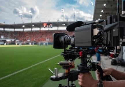
Broadcast: Broadcast fiber cables are engineered specially for the rigorous, high flex demands of live television and media production.
Shipboard: Shipboard cables feature watertight constructions that prevent flame spread and resist mechanical stress, temperature extremes, and corrosive saltwater environments.

Industrial/Mining: Ruggedized industrial fiber cables are built for factory floors, construction sites, mining, and energy operations, featuring superior flex and crush endurance alongside resistance to moisture, temperature, and chemicals.

Beyond the baseline application type, several overlapping environmental factors dictate precise fiber cable selection:
- Temperature: Environments with extreme heat or cold require cables with wider operating temperature ranges.
- Heavy traffic: Continuous vibrations from heavy machinery, traffic, or construction require ruggedized armored cable to resist crushing and mechanical impact.
- Marine/underwater: High water pressure and saltwater environments demand specialized cables that prevent water ingress and corrosion.
- Solvents/chemicals: Industrial environments that expose cables to oils, gases, jet fuels, and other harsh chemicals require fiber cables with specialized chemical-resistant jacketing.
2. Glass Type
Fiber cable is comprised of either singlemode or multimode glass strands. The glass type depends on the specific communications protocol and application standard, which dictates how data is transmitted, at what speed, and to what distance. For Ethernet communications, the IEEE develops specific application standards for singlemode and multimode fiber. Click HERE for more information on these application standards.
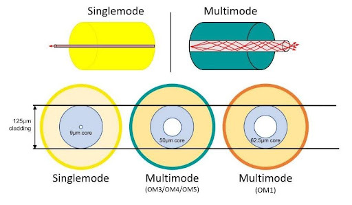
Singlemode: Designated by industry standards as OS2 and identified by a yellow outer jacket, singlemode fiber has a core diameter of 9 microns and a cladding diameter of 125 microns. It transmits data in a single mode (path) and is primarily designed for use with laser-driven transmission systems. Singlemode fiber supports higher bandwidth and distances of up to 40 kilometers (km) for long-haul and campus networks, in-building LAN backbones, and high-speed data center links.
Multimode: Featuring a larger core diameter for use with LED or lower-cost vertical-cavity surface-emitting (VCSEL) transmission systems, multimode fiber transmits data in multiple modes (paths). It is available in the following four categories as designated by industry standards:
- OM1 62.5/125: OM1 legacy multimode fiber has a core diameter of 62.5 microns and a cladding diameter of 125 microns. Rated for data transmission up to 1 Gigabit per second (Gb/s) over distances of up to 300 meters (m), OM1 is primarily used with LED-based transmission equipment and is identified by an orange outer jacket.
- OM3 50/125: OM3 laser-optimized multimode fiber has a core diameter of 50 microns and a cladding diameter of 125 microns, making it suitable for use with VCSEL transmission equipment. It can support 10 Gb/s to 300 m, 100 Gb/s up to 100 m, and high-speed 200, 400, and 800 Gb/s to 70 m. OM3 is identified by an aqua outer jacket.
- OM4 50/125: OM4 laser-optimized multimode fiber has the same core and cladding diameter as OM3 for use with VCSEL transmission equipment. It offers enhanced bandwidth capacity, enabling 10 Gb/s over 400 m, 100 Gb/s over 150 m, and high-speed 200, 400, and 800 Gb/s over 100 m. OM4 is identified by an aqua or violet outer jacket.
- OM5 50/125: OM5 laser-optimized wide-band multimode fiber has the same core and cladding diameter as OM3 and OM4. It features a broader wavelength range to support short-wavelength division multiplexing (SWDM) and BiDi transmission (transmitting data over multiple wavelengths), enabling 10 Gb/s to 550 m, 100 Gb/s to 150 m, high-speed 200 and 400 Gb/s to 150 m, and 800 Gb/s to 100 m. OM5 is identified by a lime green outer jacket.
3. Connector Specifications
When ordering custom preterminated fiber cables, you must specify the optical connector for both ends of the cable — Side A and Side B.
Connectors are either simplex (1 fiber), duplex (2 fibers), or multi-fiber (more than 2 fibers). Simplex connectors terminate a single fiber strand for one-way or bidirectional transmission using multiple wavelengths, such as in passive optical networks and fiber-to-the-home (FTTH) installations. Duplex connectors terminate two fibers for two-way data transmission (transmit and receive), either via two simplex connectors side-by-side or in a uniboot design. Duplex connectors are also used in wave division multiplexing (WDM) applications that transmit data over multiple wavelengths on two fibers.
Multi-fiber connectors are used in parallel-optic applications that transmit and receive over multiple fibers, as well as for multi-channel deployments and for consolidating backbone cabling. Note that pinned multi-fiber connectors, such as MPO/MTP, MMC, and SN-MT connectors, are designated as either male (with pins) or female (without pins). Pinned (male) connectors always mate with unpinned (female) connectors. Active equipment (switches, routers, servers, etc.) features male (pinned) ports, so any connectors that plug directly into equipment must be unpinned (female).
Depending on the operational environment and performance requirements, connectors are also available in a variety of categories, including:
- Outdoor: Designed for outside plant applications, often with an ingress protection (IP) rating of IP68 or higher.
- Rugged: Designed for harsh environments, often with an IP rating of IP68 or higher.
- Low-loss: Engineered for superior insertion-loss performance.
- Premium: Superior quality with improved alignment and mechanical reliability.
- Commercial off-the-shelf (COTS): Standardized, readily available connectors for a variety of deployments.
- Very small form factor (VSFF): Ultra-compact designs to maximize port density and save space in high-density computing environments.
- Military-grade: Built and rigorously tested for tactical field deployments, meeting MIL-SPEC standards.
The following are available connector types:
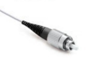
- FC connector: A simplex or duplex connector featuring a 2 .5 mm ceramic or stainless-steel ferrule and a round, threaded body that provides a secure, reliable, and dust-proof connection. FC connectors can be difficult to remove in tight spaces and require more time to form a connection due to their screw action.
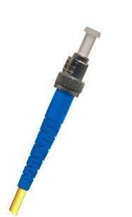
- ST Connector: A simplex or duplex connector featuring a 2.5 mm round keyed ferrule and a spring-loaded twist-on/twist-off bayonet-style action for a stable, secure connection. ST connectors are available in premium, rugged, stainless steel, and military grade (M83522/MIL-ST) options.
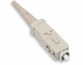
- SC Connector: A simplex or duplex connector featuring a 2.5 mm ferrule with a push-pull action that eliminates the need for any screw- or twist-on action, offering easier insertion and removal. SC connectors are available in outdoor, premium, and rugged options.
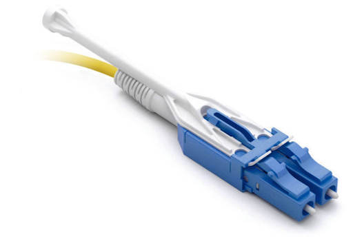
- LC Connector: A simplex or duplex connector featuring a smaller 1.25mm ferrule, excellent insertion loss performance, and a plug latch for a secure connection. Duplex versions often feature a uniboot design with a push-pull tab for easy insertion and removal. LC connectors are available in outdoor, premium, low-loss, and rugged options. The Senko IP-16 LC is designed for outdoor and harsh environments with an IP68 protection rating.
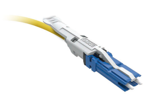
- CS Connector: A duplex 1.25mm VSFF connector from Senko with less spacing between fibers and a smaller housing, offering 40% higher density compared to the LC. Click HERE to learn more.
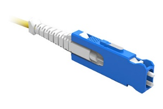
- SN Connector: A duplex 1.25mm VSFF connector from Senko with vertically oriented fibers for a reduced connector housing width, offering 3X higher density than the LC. Click HERE to learn more.
- MDC Connector: Like the SN, a duplex 1.25 mm VSFF connector from US Conec with vertically oriented fibers for a reduced connector housing width, offering 3X higher density than the LC. Click HERE to learn more.
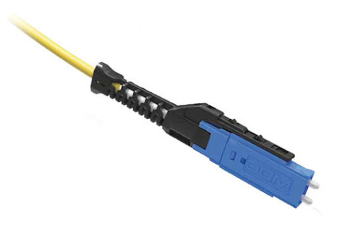
- MPO/MTP8: 8-fiber pinned connector available in male (pinned) or female (unpinned) configurations, often used to support 8-fiber parallel-optic applications. MPO/MTP8 connectors have a center key and can mate with MPO/MTP12 connectors.
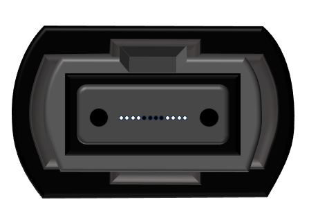
- MPO/MTP12: 12-fiber pinned connector available in male (pinned) or female (unpinned), often used in consolidated duplex backbone cabling via MPO/MTP-to-duplex cassettes. MPO/MTP12 connectors have a center key and can mate with MPO/MTP8 connectors.
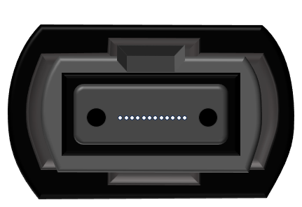
- MPO/MTP16: 16-fiber pinned connector available in male (pinned) or female (unpinned) configurations, often used to support 16-fiber parallel-optic applications. MPO/MTP16 connectors have an offset key and cannot mate with MPO/MTP8, MPO/MTP12, or MPO/MTP24 connectors.
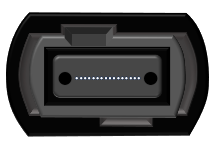
- MPO/MTP24: 24-fiber pinned connector available in male (pinned) or female (unpinned) used in consolidated backbone cabling via MPO/MTP-to-duplex cassettes or for breaking out to three MPO/MTP-8 connections. While MPO/MTP24 connectors have a center key, they feature two rows of 12 fibers and cannot mate with MPO/MTP8 and MTP/MTP12 connectors.
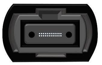
- MMC: This multi-fiber VSFF connector from US Conec is a low-loss 12-fiber (MMC12) or 16-fiber (MMC16) connector with vertically oriented fibers to provide nearly 3X the density of a traditional MPO/MTP connector. It features push-pull boot technology for easy insertion and removal. It is ideal for breakout applications and ultra-high-density 16-fiber 400 and 800 Gb/s applications. It also comes in a 24-fiber (2X12) MMC II version that is not compatible with the MMC16. Click HERE to learn more about MMC connectors.
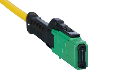
- SN-MT: Like the MMC, the SN-MT connector from Senko is a low-loss, 16-fiber VSFF connector with vertically oriented fibers to provide nearly 3X the density of a traditional MPO/MTP connector. It also features push-pull boot technology for easy insertion and removal. It is ideal for breakout applications and ultra-high-density 16-fiber 400 and 800 Gb/s applications. Click HERE to learn more.
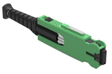
- MPO Outdoor IP-16 (Senko): 12- or 24-fiber pinned MPO connector available in male (pinned) or female (unpinned), featuring an IP68-rated, ruggedized design for outdoor connections.
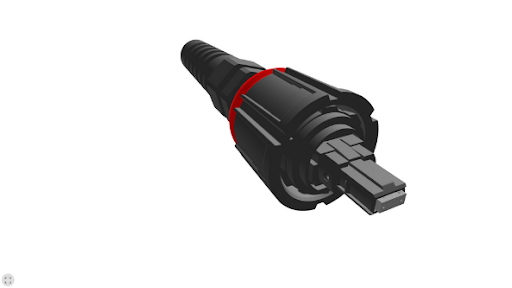
- MPO Outdoor IP-9 (Senko): An ultra-compact version of the 12- or 24-fiber pinned IP-16 MPO connector available in male (pinned) or female (unpinned) configurations, featuring an IP68-rated, ruggedized design for outdoor connections.
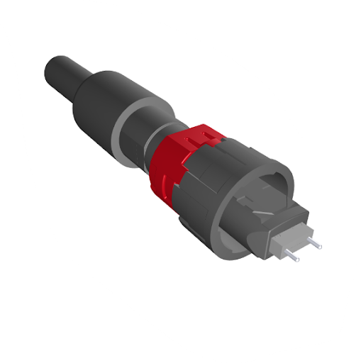
- MHC-T2 (OCC): A mini genderless rugged cylindrical connector available in 2-, 4-, 6-, and 8-channel configurations with an IP68 rating for industrial, harsh, and broadcasting environments.
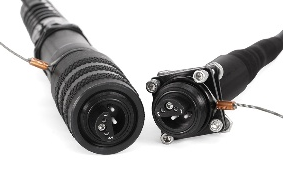
- MHC-T3 (OCC): A compact, genderless rugged cylindrical connector with proven MT technology for 12-, 24-, or 48-fiber configurations with an IP68 rating for industrial, harsh, and broadcasting environments.
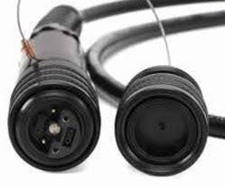
- MT38999: Qualified for use in harsh military, defense, aerospace, and naval applications requiring high shock and vibration resistance, MT38999 rugged, high-density circular connectors feature a 12- or 24-fiber MT ferrule arranged in a single-cavity MIL-DTL-38999 Series III shell size 11. They are also available in a four-cavity MIL-DTL-38999 Series III shell size 21 to support four 12-fiber MT ferrules (48 fibers).
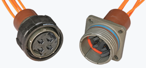
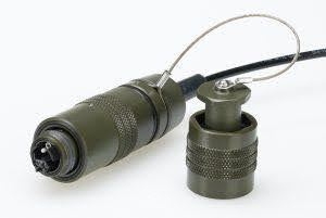
- D38999: Based on the MIL-DTL-38999 Series III standard for use in harsh military, defense, aerospace, and naval applications, D38999 connectors are rugged, circular connectors with individual pins and sockets for applications requiring fewer fibers. D38999 receptacles can be wall-mount style for mounting through a panel or bulkhead or for accepting a backshell. They can also be a jam nut style for mounting into a round panel hole using a threaded hex nut for an environmentally sealed connection.
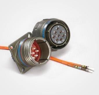
- M28876: Based on the MIL-DTL-28876 standard, M28876 connectors are rugged, circular fiber connectors for use in harsh military and naval applications, including submarines. They offer excellent optical alignment and mechanical durability and come in a variety of configurations, shell mounting styles, and backshell angles for bulkhead and panel installations, inline cable extension, and secure jam-nut receptacles for sealed enclosures.
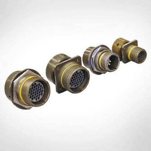
- M25904: Based on the MIL-PRF-29504 standards, M25904 pin and socket optical termini are used in hermaphroditic EZ-MATE connectors that offer superior resistance to harsh mechanical and environmental conditions and quick deployment without male/female distinctions in advanced military tactical deployments, ship-to-shore communications, mobile or remote broadcast, and oil and gas applications. They come in 2-4, 4-6, 8-12, and 18-24 channel plug and receptacle configurations, including jam-nut and flange-mount receptacles. Click HERE for more information.
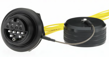
- M83526: Based on the MIL-DTL-83526 standards, M83526 Tactical Fiber Optic Cable Assembly (TFOCA) connectors are rugged, hermaphroditic fiber connectors designed for harsh military and field tactical environments. They offer quick, tool-less connections without male/female distinctions and come in 2-, 4-, 6-, and 12-channel plug and receptacle configurations, including jam-nut and flange-mount receptacles. Click HERE for more information.
4. Polish Type
In addition to the connector type, you also need to specify the polish finish type for the ferrule endface of the connectors. The commonly recognized polishes are Ultra Physical Contact (UPC), which is polished with a slight dome curvature to optimize core-to-core contact, or Angled Physical Contact (APC), which is polished at an 8-degree angle for superior reflectance performance. Used primarily with OM1 legacy fiber, a Physical Contact (PC) connector is an older style endface that features a less pronounced curvature than UPC ferrules.
UPC connectors are often designated with a blue connector housing, and APC with a green connector housing. Most multimode connectors feature a UPC endface, except for multi-fiber MPO/MTP, MMC, and SN-MT connectors used in high-speed 200, 400, and 800 Gb/s applications. Singlemode simplex and duplex connectors can be UPC or APC.
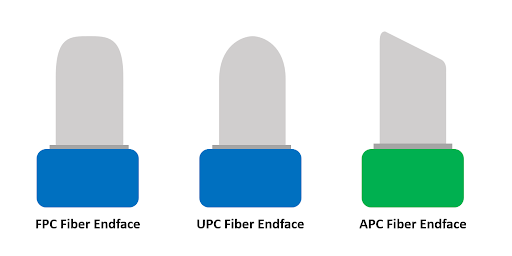
Note that all multi-fiber singlemode connectors (MPO/MTP, MMC, and SN-MT) feature an APC polish because it is too difficult to achieve adequate reflectance across multiple fibers with a UPC polish. It’s also important to remember that UPC and APC connectors cannot mate, and mating two APC connectors requires proper orientation to align the angles. Click HERE to learn more about fiber endface polishes.
5. Cable Construction
Fiber optic cable comes in two primary constructions—loose tube and tight buffered. Loose tube cables are the industry standard for outside plant applications, including aerial, direct-buried, and underground conduit installations. These outdoor versions feature 250- or 200-micron fibers loosely contained within protective plastic tubes filled with gel or other water-blocking material to prevent water penetration. Loose-tube cables are also available in dry designs with aramid yarn (Kevlar) for tensile strength, which are used for indoor applications with multi-fiber connectivity. Individual tubes in a loose-tube cable typically contain 12 fibers each, with higher-count designs incorporating a center strength member. Loose tube fiber can also be constructed in a ribbon configuration where individual fibers are bonded together in a flat strip, typically in sets of 12, for mass fusion splicing.
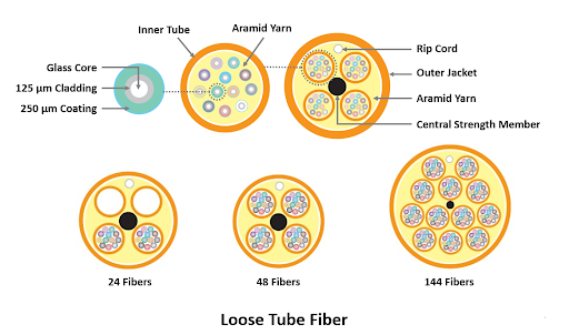
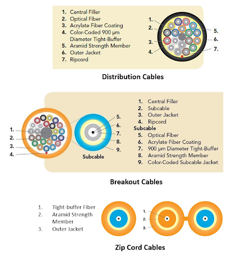
Tight-buffered cables are used for inside applications and feature a 900-micron protective layer over the 250-micron fibers, which are surrounded by aramid yarn. They are also available in indoor/outdoor versions that can traverse between buildings and feature some form of water blocking to prevent ingress. Tight-buffered cables come in various constructions:
- Distribution cables: Individual 900-micron coated fibers bundled together in a single outer jacket, resulting in a smaller, lighter-weight cable that's ideal for LAN backbones and where space is limited.
- Breakout cables: Individually jacketed, tight-buffered fibers bundled together within the cable that can be easily broken out for separate connections to devices or spaces. The fibers can also be subgrouped into individual manageable subunits in the cable, typically containing 12 or 16 fibers each.
- Zip cord cables: Individually jacketed fiber cables joined together by a thin web of jacket material (much like a zipper), allowing them to be easily pulled apart for creating two distinct pathways or to branch off services mid-span.
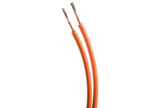
Both loose tube and tight-buffered cables can also be constructed with a protective armor layer for physical durability. The most popular type of armor is aluminum interlocking armor (ILA), which uses coiled aluminum wrapped around the cable. Armor can also be corrugated steel tape (CST), which is popular in outside-plant applications for protection against mechanical impacts and rodent damage.
6. Strand Count
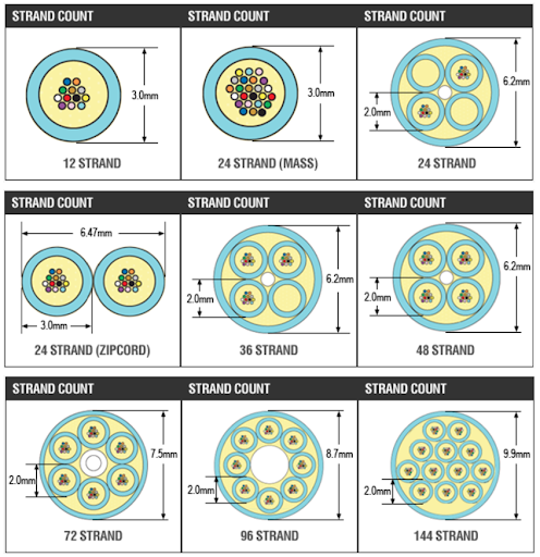
Fiber cable is available in a variety of strand counts, including 2, 4, 6, 8, 12, 18, 24, 36, 48, 72, 144, and 288. Selection depends on the application standard, the number of connections, and the desired level of redundancy and futureproofing.
A combination of the number of connections and the application standard is primarily what determines the required strand count. For example, duplex applications use two fibers per connection — one fiber to transmit data and one to receive data. If you need a cable that supports 12 duplex connections, you will need a 24-fiber cable. WDM applications that transmit data over multiple wavelengths on a single fiber also typically use two fibers per connection.
In contrast, parallel optic applications transmit and receive data over multiple fibers to achieve higher data rates. Depending on the signaling rate (speed per fiber), a parallel optic link typically requires 8 fibers (4 transmitting and 4 receiving) or 16 fibers (8 transmitting and 8 receiving). For these applications, it's common to see fiber counts of 12, 24, 48, 72, 144, and 288, which can be broken out into multiple 8- or 16-fiber connectors.
Strand count also depends on the desired level of redundancy and futureproofing. For example, in a LAN backbone connecting telecom spaces with 6 duplex connections (12 fibers), it's common to deploy 24-fiber cable for redundancy and/or support future needs.
NOTE: It’s important to understand that strand counts come in multiple constructions. When ordering a strand count of 24, the cable can be a “mass” distribution cable containing 24 tight-buffered fibers bonded together under a single jacket, a “zipcord” cable consisting of two 12-fiber cables joined together, or a unitized/breakout cable with individually jacketed cables or subgrouped into two 12-fiber sub-units.
7. Jacket Rating
When purchasing custom fiber cables, you also need to specify jacket rating. This is especially important for indoor cables to comply with the National Electric Code (NEC), ensure building safety, and pass inspections. For indoor cables, the most common jacket ratings include:
- Optical Fiber Non-Conductive Plenum (OFNP): Plenum-rated cables meet the strictest fire and smoke standards for use in plenum spaces, which are areas used for environmental air circulation throughout a building. This includes drop ceilings used for HVAC air returns, raised-floor air distribution systems, and air ducts or air-handling pathways. They comply with NFPA-262 and UL-910.
- Optical Fiber Non-Conductive Riser (OFNR): Riser-rated cables are designed for vertical cable runs between floors through vertical conduits, cable risers, utility shafts, or elevator shafts. Riser cables are engineered to self-extinguish and prevent flame propagation during vertical burn tests. They cannot be installed in plenum spaces and comply with UL-1666.
- Low-smoke, zero-halogen (LSZH): LSZH cables minimize toxic gas emissions and smoke during combustion. They do not contain halogens, such as fluorine, chlorine, bromine, or iodine. LSZH cables are commonly used in environments where safety and equipment protection are critical, such as shipboard installations, data centers, underground transportation tunnels, and areas with limited ventilation. Note that LSZH cables alone do not meet plenum or riser ratings.
Equipment cords and patch cables used in open commercial building areas that are not required to be plenum, riser, or LSZH are considered general purpose and designated as simply Optical Fiber Non-Conductive (OFN). Click HERE to learn more about jacket ratings.
8. Cable Length
Specifying the correct cable length is critical when ordering custom fiber cables, as they are cut to exact specifications with no field adjustability. Cables that are too short may not reach the intended termination point, or they risk getting pulled too tight and damaging the fiber. Cables that are too long result in excess slack that needs to be effectively managed to avoid creating a messy “spaghetti” of wires.
Tips for ordering the right cable length include:
- Measure the exact intended cable path, accounting for every corner, turn, and vertical drop. Factor in the minimum bend radius to prevent the fiber from being bent too tightly or kinked during installation.
- Add 10% to 20% to the total physical length to account for elevation adjustments, cable management, and future reterminations.
- Consider the application and be sure the length of the cable is within the maximum distance limitation per industry standards.
9. Fanout/Breakout Length and Style
When ordering custom fiber cables, you may need a fanout (breakout) cable to transition from outdoor cable to indoor cable, accommodate field termination, or support hybrid breakout applications. To transition from outdoor to indoor cable, 250µm fiber breakouts are used to accommodate fusion splicing or to transition to 900µm fiber for termination. In contrast, 900µm fiber breakouts are used for direct field-termination to connectors.
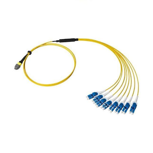
Breakout cables can also be preterminated hybrid cables that typically use multi-fiber connectors on one end and duplex connectors on the other, supporting breakout applications where a high-speed multi-fiber parallel-optic switch port connects to multiple lower-speed duplex ports. For example, a cable with an MPO/MTP8 on one end and four duplex connectors on the other end can be used to break out an 8-fiber 400 Gig switch port to four duplex 100 Gig connections. Hybrid preterminated breakout cables can also include higher-count multi-fiber connectors on one end that connect to lower-count multi-fiber connectors on the other end, such as a single 16-fiber 800 Gig switch port that breaks out to two 8-fiber 400 Gig connections. Click HERE to learn more information on breakout applications.
There are two key parameters to consider when ordering breakout cables.
- Fanout length: Also known as the furcation length, it is the distance from the transition point to the final connector termination point or connector tips along the individual breakout legs (or tails). It does not include the main cable body. For hybrid breakout applications using preterminated connectors, this length is determined by the distance from where the breakout will be mounted to the farthest point it needs to reach, plus a few extra inches to account for bend radius and minimize strain.
- Fanout style: Fanouts can be bare 250µm loose-tube or 900µm tight-buffer fibers for fusion splicing or direct field termination. Note that 250µm breakouts typically require a breakout kit to transition to 900µm for connector termination. Multi-fiber cables can also be preterminated to connectors via 2mm or 3mm furcations.
10. Polarity
Polarity is a critical parameter when ordering custom fiber optic cables. It ensures that the transmit (Tx) signals at one end of a channel correctly map to the receiver (Rx) signals at the other end. Without proper polarity, the data signal will not flow.
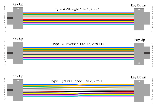
End-to-end duplex polarity is straightforward with A-B duplex patch cords providing a straight-through connection to maintain polarity. However, polarity becomes more complex when using multi-fiber MPO/MTP connectivity. There are essentially three primary polarity methods for multi-fiber links — A, B, and C. These methods use a variety of Type A, Type B, and Type C cables, adapters, and patch cords.
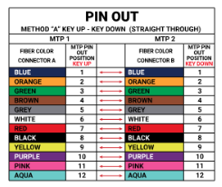
- Method A: Uses Type A straight-through key-up to key-down cables, where position 1 at the near end corresponds with position 1 at the far end. Method A requires a Type B patch cord at one end of the channel.
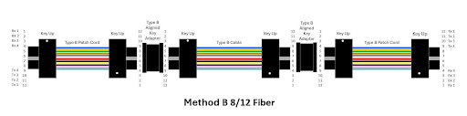
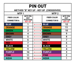
- Method B: Uses Type B reversed key-up to key-up cables, where position 1 at the near end corresponds with the last position (12, 16, 24, etc.) at the far end. Method B uses Type B patch cords at both ends of the channel. Method B is the recommended method since it maintains the same patch cords on both ends.
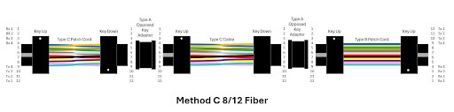
- Type C: Uses Type C cross-over key-up to key-down cables, where the fiber pairs are flipped so position 1 at the near end corresponds with position 2 at the far end. Type C works well for duplex breakout applications but is not recommended for parallel optics as it would require a complex (and typically unavailable) Type C crossover patch cord at one end of the channel to reverse the pair flip.
It is highly recommended to choose one polarity method and stick to it throughout your entire cabling plant — mixing methods requires maintaining varied inventory and causes confusion that can result in breaking TX-to-Rx mapping. Additionally, when designing channels comprised of multiple link segments (trunks and patch cords), the polarity must be determined and maintained across all links in the channel. Don’t forget that male (pinned) MPO/MTP connectors can only mate with female (unpinned) MPO/MTP connectors, and that the active equipment uses a male (pinned) interface.
8/12 Fiber Polarity
Polarity for 8-fiber and 12-fiber links is essentially the same since MPO/MTP8 connectivity uses the same form factor as MPO/MTP12 connectivity, but with the four center fibers removed.
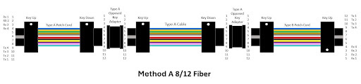
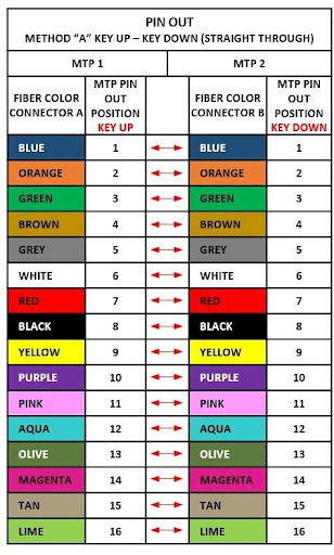
- Method A: Uses a straight through Type A cable where the fiber in Position 1 on one end arrives at Position 1 on the other end. The channel uses Type A opposed key adapters, a Type A patch cord on one end, and a Type B patch cord on the other.
- Method B: Uses a reversed Type B cable where the fiber in Position 1 on one end arrives at Position 12 at the other end. The channel uses Type B aligned key adapters with Type B patch cords on both ends. When using APC MPO/MTP connectors, a key-down to key-up configuration is required, which is achieved with Type A opposed key adapters that change the orientation of the Type B cable.
- Method C: Uses a flipped Type C cable where the fiber in Position 1 arrives at Position 2 at the other end and Position 2 arrives at Position 1. The channel uses Type A opposed key adapters and a Type B patch cords on one end and a Type C cross-over patch cord at the other end to reverse the pair flip. Method C is not recommended for parallel optics.
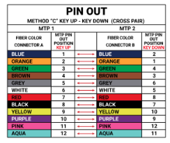
16 Fiber Polarity
Polarity for 16-fiber links is essentially the same as 8/12 fiber polarity but with 16 fiber positions.
- Method A: Uses a straight through Type A cable where the fiber in Position 1 on one end arrives at Position 1 on the other end. The channel uses Type A opposed key adapters, a Type A patch cord on one end, and a Type B patch cord on the other.
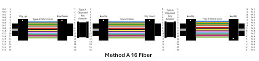
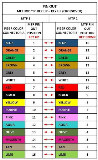
- Method B: Used a reversed Type B cable where the fiber in Position 1 on one end arrives at Position 16 at the other end. The channel uses Type B aligned key adapters with Type B patch cords on both ends. When using APC MPO/MTP connectors, a key-down to key-up configuration is required, which is achieved with Type A opposed key adapters that change the orientation of the Type B cable.
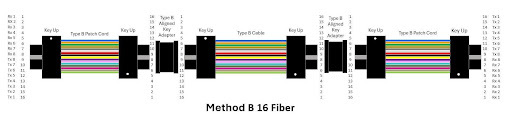
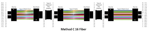
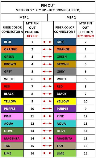
- Method C: Uses a flipped Type C cable where the fiber in Position 1 arrives at Position 2 at the other end and Position 2 arrives at Position 1. The channel uses Type A opposed key adapters and a Type B patch cord on one end and a Type C cross-over patch cord at the other end to reverse the pair flip. Method C is not recommended for parallel optics.
24 Fiber Polarity
Polarity for 24-fiber links is more complex because the MPO/MTP connectors feature a two-row interface. Method B is recommended to maintain the same jumper types on both ends.
- Method A: Uses a straight-through Type A cable where the fiber in Position 1 (Top Row) on one end arrives at Position 13 (Top Row) on the other end. The channel uses Type A opposed key adapters, a Type A patch cord on one end, and a Type B patch cord on the other.

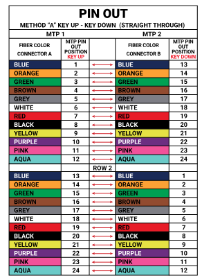
- Method B: Used a reversed Type B cable where the fiber in Position 1 (Top Row) on one end arrives at Position 24 (Bottom Row) at the other end. The channel uses Type B aligned key adapters with Type B patch cords on both ends. When using APC MPO/MTP connectors, a key-down to key-up configuration is required, which is achieved with Type A opposed key adapters that change the orientation of the Type B cable.

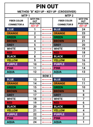
- Method C: Uses a flipped Type C cable where the fiber in Position 1 (Top Row) arrives at Position 14 (To Row) at the other end and Position 2 arrives at Position 1. Uses Type A opposed key adapters and a Type B patch cord on one end and a Type C cross-over patch cord at the other end to reverse the pair flip. Method C is not recommended for parallel optics.

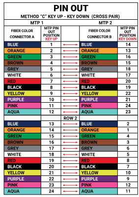
24 Fiber Polarity for Cassette-to-Cassette Links
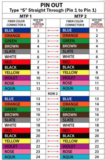
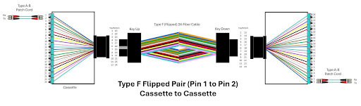
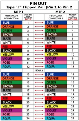
When using 24-fiber trunk cables to connect high-density 24-port cassettes, Type “S” Straight Through (Pin 1 to 1) or Type “F” Flipped Pair (Pin 1 to 2) trunks are used to maintain polarity.
- Method A / Type S Trunk: A Type S 24-fiber key-up to key-down trunk transmits straight-through, so the fiber in Position 1 (Top Row) arrives at Position 1(Top Row), Position 24 (Bottom Row) arrives at Position 24 (Bottom Row), and so on. This requires Type A-B patch cords on one end of the channel and Type A-A patch cords on the other end.
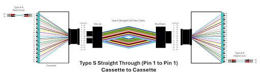
- Method C/Type F Trunk: A Type F 24-fiber key-up to key-down flips the fibers, so the fiber in Position 1 (Top Row) arrives at Position 2 (Top Row) and Position 2 (Top Row) arrives at Position 1 (Top Row), and so on. This uses Type A-B duplex patch cords on both ends of the channel.
11. Additional Specs to Consider
Additional specifications to consider when ordering custom fiber cables include the following:
- Pulling Eye: Helps protect cables during installation by providing a pulling point to properly distribute tension while protecting connectors. You can specify pulling eyes on one or both ends of a custom cable.
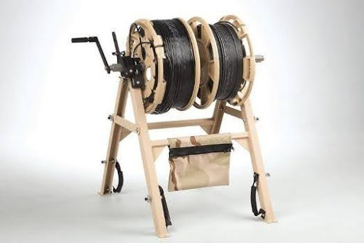
- Reel: Cables Plus USA offer a wide range of deployable cable reels designed for a variety of applications. Cables can be supplied on wood or plastic reels. Options also include modular advanced reel system (MARS) tactical military reels made from durable polymer for harsh environments, heavy-duty Shane military reels built with full steel construction, and Hannay and Carare rugged audio/video metal reels. Click HERE to learn more about reels.
- Quantity: Don’t forget to indicate how many of each custom cable you need. If the budget allows, you may want to order extra cables to have spares available.
We’re Here to Help!
The good news is that you don’t have to navigate ordering custom cables alone. At Cables Plus USA, our team of experts is ready to help you review your specifications and make sure you order the right custom fiber cable for your specific needs. Contact us today to get started!
We also have several educational blogs on our website to help you specify custom cables. Following are a few of our favorites sorted by topic:
General Knowledge:
- Standard vs. Custom Fiber Optic Cables
- Why Talking to a Human Still Matters When Choosing a Fiber Optic Cable Supplier
- Assessing Network Requirements to Determine Fiber Optic Needs
- Decoding Ethernet Application Names: The Ultimate Technical Guide
Fiber Optic Cabling:
- How to Choose the Right Fiber Optic Cables
- Plenum vs. Riser vs. General Purpose: Understanding Cable Fire Ratings
- Multimode Fiber Cabling Types: From OM1 to OM5
- MPO/MTP Trunk Cables vs. Breakout Cables
- Optimize Your Data Center with 400 Gig Breakouts
- Best MPO/MTP Cables for Switch-to-Switch Connections
Fiber Optic Connectivity:
- Ultra-Low Loss Fiber Connectivity: Why It Matters in Modern Data Centers
- New High-Density Duplex Connectors
- Understanding LC Connectors: The Cornerstone of Fiber Optic Networks
- Fiber Optic Patch Cable Connector Types & Their Uses
- MTP vs MPO: What's the Difference & Why You Should Care
- Get Ready for 16-fiber Small Form Factor Connectors!
- MPO/MTP vs MMC: A Density Comparison
- A Guide to Fiber End Face Shape and Polish